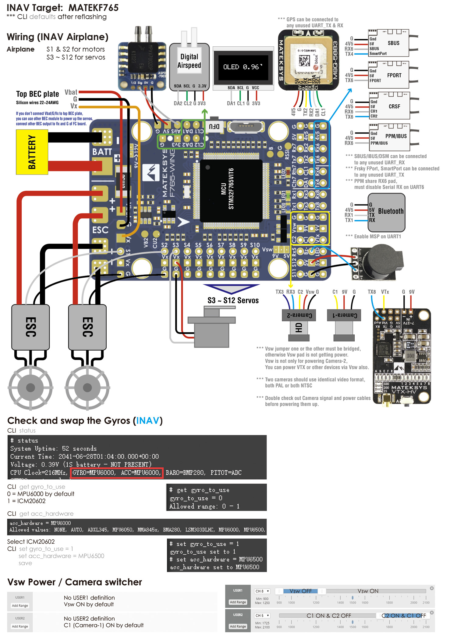
MATEKSYS FLIGHT CONTROLLER F765-WING
Out of stock
SKU
OA02898
Special Price
₹5,895.00
Regular Price
₹6,968.53
F765-WING Quick Start Guide (PDF 9M)
FC Specifications
- MCU: STM32F765VIT6, 216MHz , 512KB RAM, 2MB Flash
- IMU: MPU6000 (SPI1) & ICM20602 (SPI3)
- Baro: BMP280 (I2C2)
- OSD: AT7456E (SPI2)
- Blackbox: MicroSD card slot (SDIO)
- 7x Uarts (1,2,3,4,6,7,8) with built-in inversion.
- 1x Softserial1_Tx (INAV)
- 12x PWM outputs (S1~S10 support Dshot)
- 6x ADC (VBAT, Current, RSSI, Analog AirSpeed, VB2, CU2)
- 3x LEDs for FC STATUS (Blue, Red) and 3.3V indicator(Red)
- 2x I2C
- 1x SPI4 breakout
- Switchable Dual Camera Inputs
- Switchable 5V/9V(12V) for Camera/VTX
- High-precision Current Sense
- ADC VB2 voltage divider: 1K:10K
- ADC AirSpeed voltage divider: 10K:10K
- TR/SA VTX control: Yes
- WS2812 Led Strip : Yes
- Beeper : Yes
- RSSI: Yes
- Analog Airspeed sensor: Yes
- Digital Airspeed sensor: Yes
FC Firmware
- INAV Target: MATEKF765
- ArduPilot(ChiBiOS) Target: MATEKF765-WING
PDB
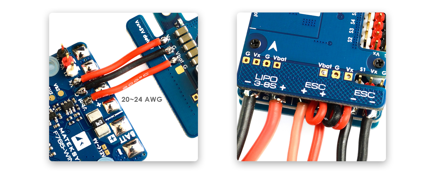
- Input voltage range: 9~36V (3~8S LiPo) w/TVS protection
- 2x ESC power pads
- Battery Voltage Sensor: 1:10 (Scale 1100 in INAV, BATT_VOLT_MULT 11.0 in ArduPilot)
- Current Senor: 132A, 3.3V ADC (Scale 250 in INAV, 40 A/V in ArduPilot)
BEC 5V output
- Designed for Flight controller, Receiver, OSD, Camera, Buzzer, 2812 LED_Strip, Buzzer, GPS module, AirSpeed
- Continuous current: 2 Amps, Max.3A
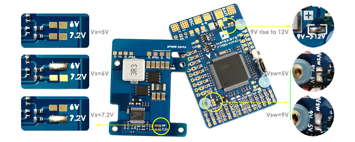
BEC 9V /12V output
- Designed for Video Transmitter, Camera, Gimbal ect.
- Continuous current: 2 Amps, Max.3A
- 12V option with Jumper pad
BEC Vx output
- Designed for Servos
- Voltage adjustable, 5V Default, 6V or 7.2V via jumper
- Continuous current: 8 Amps, Max.10A
BEC 3.3V output
- Designed for Baro / Compass module and Spektrum RX
- Linear Regulator
- Continuous current: 200mA
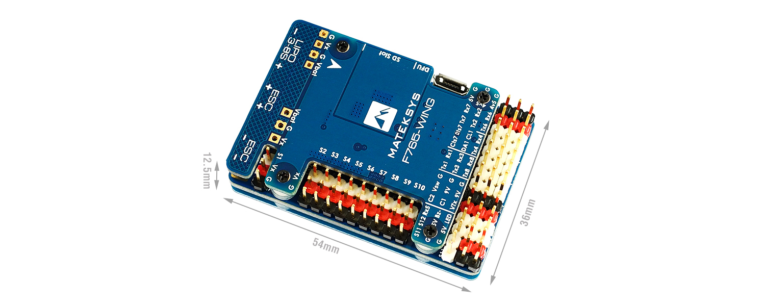
Physical
- Mounting: 30.5 x 30.5mm, Φ4mm with Grommets Φ3mm
- Dimensions: 54 x 36 x 13 mm
- Weight: 26g
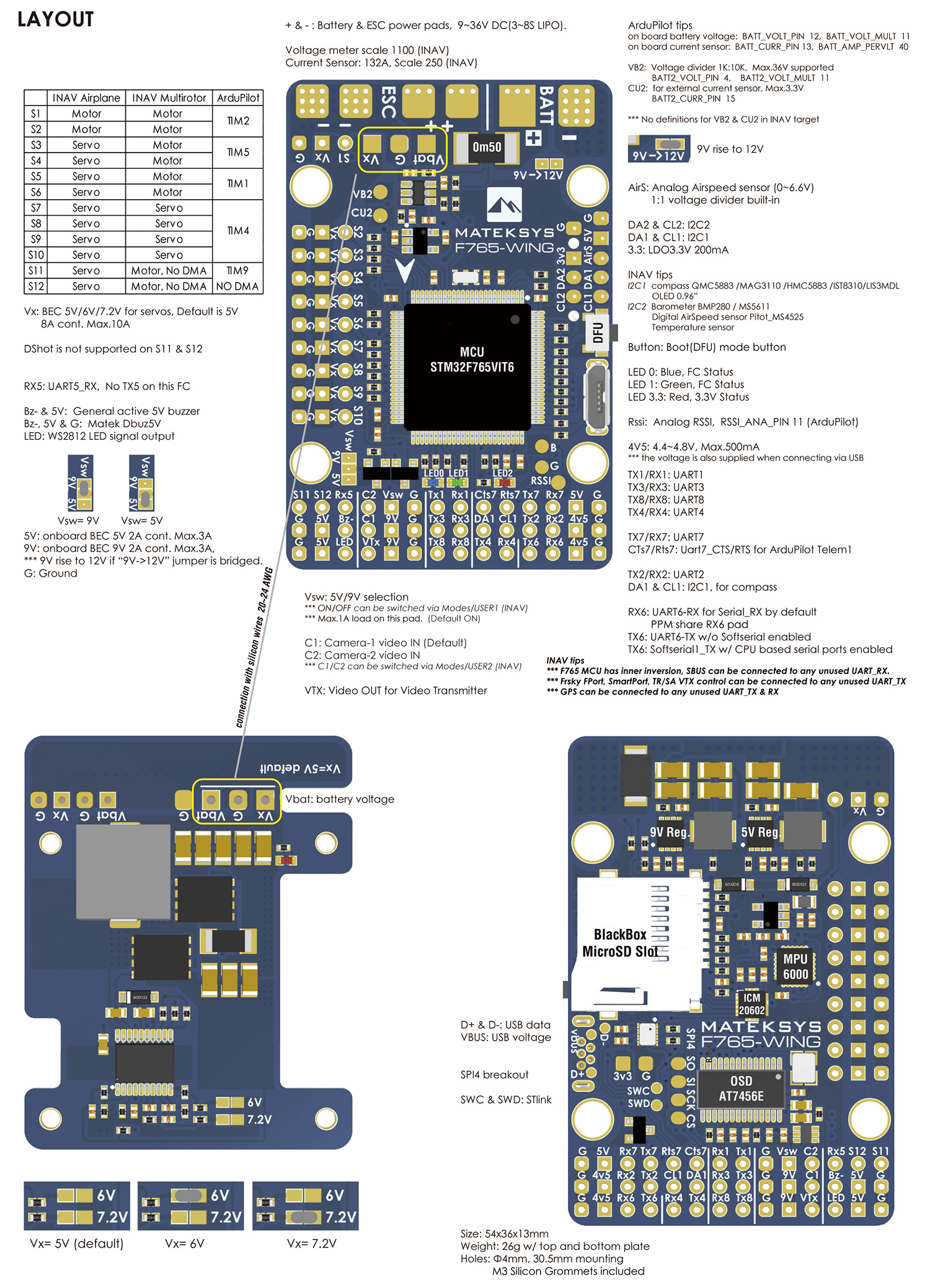
| PWM
Motor can’t share same TIM with servo. |
S1 | Group1 | TIM2 | |
| S2 | ||||
| S3 | Group2 | TIM5 | ||
| S4 | ||||
| S5 | Group3 | TIM1 | ||
| S6 | ||||
| S7 | Group4 | TIM4 | ||
| S8 | ||||
| S9 | ||||
| S10 | ||||
| S11 | Group5 | TIM9 NO DMA |
||
| S12 | ||||
| ADC | No pad | on board battery voltage | BATT_VOLT_PIN | 12 |
| on board battery voltage | BATT_VOLT_MULT | 11.0 | ||
| No pad | on board current sensor | BATT_CURR_PIN | 13 | |
| on board current sensor | BATT_AMP_PERVLT | 40 | ||
| VB2 Pad | VB2 ADC | BATT2_VOLT_PIN | 4 | |
| VB2 voltage divider | BATT2_VOLT_MULT | 11.0 | ||
| CU2 Pad | CU2 ADC | BATT2_CURR_PIN | 15 | |
| external currenr sensor scale | BATT2_AMP_PERVLT | / | ||
| RSSI Pad | RSSI ADC | RSSI_ANA_PIN | 11 | |
| Analog RSSI | RSSI_TYPE | 1 | ||
| AirS Pad | AirS ADC | ARSPD_PIN | 10 | |
| Analog Airspeed | ARSPD_TYPE | 2 | ||
| I2C | I2C1 or I2C2 | Digital Airspeed I2C | ARSPD_BUS | 1 |
| Digital Airspeed | ARSPD_TYPE | 1 | ||
| I2C1 or I2C2 | Compass | COMPASS_AUTODEC | 1 | |
| I2C2 | on board BMP280 | |||
| UART | USB | console | SERIAL0 | |
| UART7 | telem1 | SERIAL1 | ||
| USART1 | telem2 | SERIAL2 | ||
| USART2 | GPS1 | SERIAL3 | ||
| USART3 | GPS2 | SERIAL4 | ||
| UART8 | USER | SERIAL5 | ||
| UART4 | USER | SERIAL6 | ||
| UART5 | not supported for now | |||
| USART6 | RC input/Receiver | |||
| RX6 | SBUS | |||
| RX6 | PPM |
- Camera-1 and Vsw On by default
- Be sure 2 cameras are set with identical video format, both PAL or both NTSC.
# GPIOs
- PE4 PINIO1 OUTPUT GPIO(81) //Vsw pad power switch
- PE15 PINIO2 OUTPUT GPIO(82) //Camera switch
# RCx_OPTION: RC input option
- 28 Relay On/Off
- 34 Relay2 On/Off
- 35 Relay3 On/Off
- 36 Relay4 On/Off
e.g.
- RELAY_PIN 81 //Vsw GPIO
- RC7_OPTION 28 //Relay On/Off, Use CH7 of Transmitter to switch Vsw
- RELAY_PIN2 82 //Camera switch GPIO
- RC8_OPTION 34 //Relay2 On/Off, Use CH8 of Transmitter to switch camera
or
- RELAY_PIN3 81 //Vsw GPIO
- RC9_OPTION 35 //Relay3 On/Off, Use CH9 of Transmitter to switch Vsw
- RELAY_PIN4 82 //Camera switch GPIO
- RC10_OPTION 36 //Relay4 On/Off, Use CH10 of Transmitter to switch camera
The configured feature will be triggered when the auxiliary switch’s pwm value becomes higher than 1800. It will be deactivated when the value falls below 1200.
Check the pwm value sent from the transmitter when the switch is high and low using the Mission Planner’s Initial Setup >> Mandatory Hardware >> Radio Calibration screen. If it does not climb higher than 1800 or lower than 1200, it is best to adjust the servo end points in the transmitter.
ArduPilot
- FPort support, details here https://discuss.ardupilot.org/t/frsky-fport-support-testers-wanted/50669
- PWM 5 & 6 not working in ArduPilot firmware has been fixed in latest firmware later than Oct.30 https://github.com/ArduPilot/ardupilot/pull/12685
- External MS5611 has been supported on F765-WING with latest ArduPilot firmware, Hook up MS5611 module to I2C1(CL1,DA1) or I2C2(CL2,DA2), set GND_PROBE_EXT = 4 for the MS5611. GND_PRIMARY = 1 to use the external barometer as the primary
——————————
- Camera-1 and Vsw On by default.
- If using 2 cameras, both should be set with identical video format, both PAL or both NTSC.
- Rx5 is not supported for now.
- If FC board and top BEC plate are not connected via Vbat/G/Vx , you might solder other BEC output to FC Vx and G pad for powering up servos.
——————————
- No VB2 and CU2 definitions in INAV target
- OSD font uploading could break off in MacOS INAV configurator, pls use Windows version.
-
RCG Thread Matek F765 Wing Flight Controller w/Ardupilot (ChiBiOS)
- Review by Paweł Spychalski
- Review by Painless360
| Brand | MATEK |
|---|
Write Your Own Review
Customer Questions
Who Viewed This Also Viewed
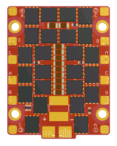
Aikon Race Dragon RD32 4-in-1 45A 6S
Special Price
₹5,243.16
Regular Price
₹6,196.47
ETHIX XT30 RUBBER (20PCS)
Special Price
₹676.81
Regular Price
₹766.00
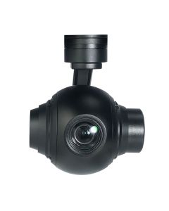
Viewpro Q10F 3-Axis 10X Zoom Camera Gimbal
Special Price
₹116,351.32
Regular Price
₹130,217.41
TCMMRC TS140 140mm Wheelbase 2.5mm Arm Carbon Fiber FPV Racing Frame Kit
Special Price
₹1,590.13
Regular Price
₹1,879.25